By the end of this project i will know the difference between a hard surface and a organic surface but also model a real life building.
What are UV's
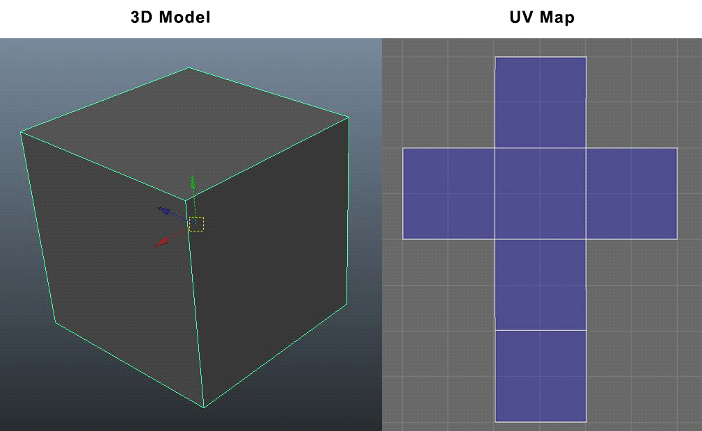
The letter "U" and "V" are used as the axes for 2d texture because "X", "Y" and "Z" are already in use for 3d modelling. UV's allow the texture to be placed on a 3d model object using a 2d texture.
How to UV with Maya
There are six different techniques used to create UV's in Maya.
0-1 UV Space
Most software's have a "UV" editor panel of some type that has a grid where you place the UV's. Some of them have just a "positive" space and others have a "negative" space. Maya's UV editor has a grid ranging from -1 to -1 on both the U and V axis. Highlighted in pink is the 0-1 space (the positive range of the UV editor). All of your UV shells must be in this space.
Working outside the UV space
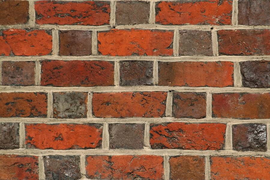
The texture will appear to repeat or wrap around the corresponding vertices when viewed in the 3D scene or rendered image. The exception to this is when you want the texture to repeat on the surface, such as a brick texture along the model of a wall or when you need a texture that repeats the same pattern.

UV Softwares
- Maya
- Blender
- Ultimate Unwrap 3D Pro
- 3D Coat
- Roadkill
Methods
- Map each Object: Map every object into UV space. It will allow you to apply texture to each object area.
-
- Polygon:(A polygon mesh is a collection of vertices, edges and faces that make up the shape of an object in 3D)
- Stretching: Stretching is always a common issue while UV mapping. It happens when polygons are in different places from their actual place or if they are not the same shape. To avoid stretches the model needs to be checked with checkers map. This needs to be placed to the model to make sure that the checkers are squares and evenly distributed. The resolution quality of the object's texture depends on how well the UV's are placed.

- Overlapping: This is where the UV goes over another map object causing it to overlap and if this happens the texture will not work.

- Reduce UV Space and Seams: This is where UV's need to be arranged and optimised as much as possible in order to keep the resolution as high as possible.

Texture Maps
Colour maps
A texture to an object’s material,which describes the colour of the object.
Transparency maps
A texture to the Transparency attribute of an object’s material, lets you make parts of an object opaque, semi-transparent, or entirely transparent.
Specular maps
A texture to the Specular attribute of an object’s material, lets you describe how shine appears on objects (by controlling highlight).
A texture to the Specular attribute of an object’s material, lets you describe how shine appears on objects (by controlling highlight).
Reflection maps
A texture to the Reflected Colour attribute of an object’s material, lets you describe how an object reflects its surroundings.
Bump maps
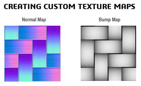
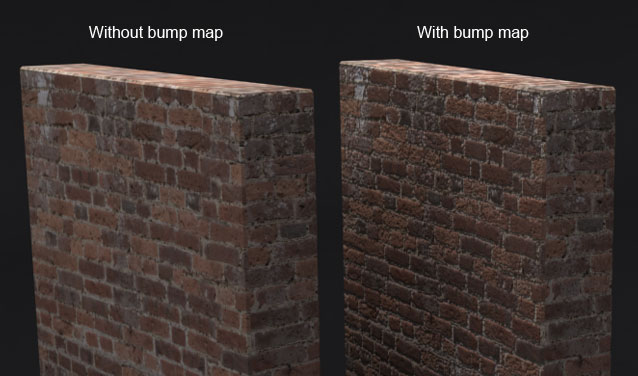
A texture to the Bump attribute of an object’s material,lets you add the illusion of surface bump detail to a surface.
Displacement maps
Displacement maps let you add true dimension to a surface at render time, a process which may reduce or eliminate the need for you to create complex models.
Transfer Maps
Transfer maps allow you to take one model and make another model look like that model through normal maps, displacement maps and bump maps.
A displacement map is real geometry (polygons), while a bump map is tricks of light to make it look like it has real geometry. Normal maps are like bump maps, as in the way they both trick the light, but normal maps actually change the surfaces normal's and bend the light. Bump map renders faster but you do lose quality. Normal maps are used more in low poly games. Displacement maps, because of their longer render time, are mostly used on objects that need high level detail.

Texture / UV Terminology
UV is where a 3D object is turned into a 2d net allowing you to create or apply textures to the object.
Texture is a raw colour to the 3D object, textures are 2D images files that are wrapped around onto an object. Photoshop is a popular choice of creating realistic textures,if we need to make the object more realistic and real we apply shaders and texture maps such as bump and reflection to make it more realistic.
Different Modelling Softwares
- Sketchup is a free user-friendly app that is used by 3D modelling beginners.
- Blender is a free 3D modelling app that is used to create sculptures, photorealistic renders and animation.
- AutoCAD is a widely used application for 3D modelling full of videos to help create environments and vehicles.
- Rhino is a 3d curve modelling software that creates mathematically precise models used for architecture, advertisements and graphic design. Rhino offers online tutorials and live classes.
- Revit is an architectural design building information modelling specialised program.
- 3Ds Max is a 3D modelling ,animation, simulation and rendering software used for film, games and motion graphics.
- Maya is a 3D modelling, animation, rendering software used to render film, games and more. Maya is used for higher end characters and effects.
- Cinema 4D is a 3D modelling animation and rendering app that is used for motion graphics , architects and 3D animation.
High poly vs Low poly
High poly is where these hundreds of points called vertexes in 2D or 3D, this means that a model with a high poly will appear to be more detailed and advanced compared to a low poly as it has more vertexes allowing it to be more detailed. The down side to High poly is that it takes long hours for a render job to be done and requires a good machine in order to render.
Low poly is the opposite of High poly meaning that there are less vertexes on a model meaning that it will be a faster render and will not require a super computer to run it, However the model will look very poorly detailed and unrealistic.

What is extruding?
Extruding is where a mesh is selected and pulled out or in to create a new geometry called a face.
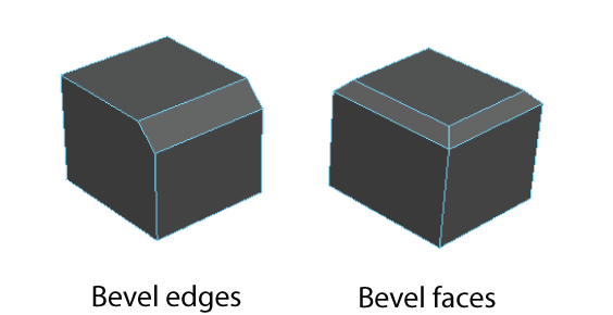
What is Bevelling?
Bevelling is where a new face is made at an angle to make edges and faces appear more rounded. This is mostly used to soften an edge or a face and to make easier to connect faces with other faces. Bevelling tool is mostly used in manufacturing when creating letters.
What is Bridging?
Bridging tool is used to close gaps between objects, this is done by joining two pieces together forming a new face filling in the gap between two points.

What is Ambient Occlusion?
Ambient Occlusion is a technique used to render lighting and shadows on a model. It works by calculating the brightness of a pixel close together and determines which pixels are blocked from getting any light from the environment. This technique is used to create film like lighting with real life performance.
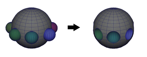
What are Booleans?
Boolean lets you combine multiple different polygon objects to create a shape that you otherwise could not make. This is done by overlapping two or more shapes onto one another forming a union.
Union: faces from both objects that intersect
Maya
Interface The menu set menu will allow you to change maya's interface depending on what your doing to make it easier for you to navigate and access shortcuts faster saving you time for example if tou go to the menu set and change it to Modelling it will change the Shortcut shelf to modelling tools to make it easier for you to access them.
The top menu is where you go to do most of the important things such as setting up a project saving the project or making the interface to your liking, the top menu is also the place where you go to when you need to render a file. Also the status line will act as a shortcut for the top menu.
The toolbox is what you will need to use if you want to edit a polygon or shape, the tool box has all the tools you need in order to make or edit any shape in any form. The right hand side is where you edit the materials and access all the modelling and menu set tools as ease.
The timeline and bottom side is most important when doing animation as you need it to add more frames to the project and add commands.
The help display is very useful when you need to find out if these any errors found or the percentage rendered when you try to render a file.
Camera
To control the camera you need to hold on alt and use any mouse key. For example the alt key and the left mouse click will allow you to move the camera around the object, this is very useful when you want to look at the object you're creating in 360 degrees. The alt and right mouse click allows you to pan just in and out and the middle mouse wheel will allow you to zoom in and out this is mostly useful when you want to look at an object from a specific angle to look at the light source or the reflection of light. Lastly the alt key and middle wheel click hold will allow you to move the camera around an object.
Hotbox
Space bar is the shortcut to use the hotbox tool and what this does is, it split the camera into 4 different view boxes allowing you to see the object from four different angles, these being top view, side view, front and the original star view. Hovering the mouse on any of the views and pressing space bar will make that view go into full screen and allow you to work on the object from that view.
Models i made in Cinema 4d
Building ideas

I've went into Maya and started to play around and get used to the new interface and the software and so far it's quite similar to Cinema 4D in terms of how easy it is to get your head around it and start modelling, the only thing i have to get used to is the new interface and the short cut keys.
Here are 10 different building ideas i can potentially choose from, these are all quite known buildings from all around the world and some of them are easy and some are hard but none are impossible to model.
The empire states building has a gorgeous design from the outside and the inside and this would be a great pick for modelling a building in any project, however the amount of detail that is needed to fully model this building would take weeks and that's something i do not have for this project. Another reason why i can't model this building is that the Empire States Building is located in New York and living in the UK means that i would have to travel all the way to the US to take screenshots for my project and come back as i am not allowed to use pictures of the internet. This would be very time consuming and very tiring as it would involve a lot of travelling.
The Louvre Pyramid located in France has a stunning glass design all around making it one of my top ten favourite buildings that i want to model, the design seems relatively easy and textures for this building would not be a problem as most of the materials in this building are transparent. The reason why i cant model this building is because this building is located in France which is not far from the UK, however it would be very annoying and stressful to keep travelling to France and back every time i needed new screenshots.
Sydney Opera House is another great building that is good for modelling as it has a nice and complex exterior, however time and travelling would be an issue so this building would need to be droped for this particular project.
The apple cube is another one of those buildings with a great transparent design and a quite nice relaxing welcoming feeling to it, and due to the building being located in the US and it being so easy to model i will have to drop this building also as it seems to easy and does not look like building which will help me get my target grade which is a merit.
The Piano House is a nice unique looking building that is not seen on a daily basis, this would be a worthy building for this project and the textures do not look that complex and i strongly believe i could finish this building on time for my project, however because of where the building is located it would be a very stressful building to do without using the internet as it would be a hassle to travel to the US and back to take screenshots.
The Big Ben is located in London which is quite far from where I live not as far as the rest but still relatively far putting it on the no list for this project.
This house is another nice challenge for this project but because of the house being located in the United States I will have to consider daily travelling which means I will have to discard it for this time and hope to use it for any future project.
The Bullring would be my second choice for this project as it is very local and travel is not an issue however the complex design and the x number of hexagonal shapes on the building would make it a nightmare for this project and I have strong feeling I would not meet the deadline with the limited time.

Stratosphere tower another great massive building for this project but again the location is a problem and as I'm not allowed to use images of the internet, I would have to go to the US which would be an issue.

In the end I have decided that the James Watt Campus is the best building to model for this project as its the most accessible to me which means I can easily take necessary reference pictures at any time during this project without having to worry about travel.
Grid Setup in Maya
Setting up a grid in Maya to match the unreal engine grid is very easy. First thing is you need to know that 1 unreal unit is equivalent to 1 centimetre this means that if you were to make a grid 5 meters long you would need to make sure that you put the measurements of 500 centimetres in Maya.
To access the grid in Maya you go up to the Display window and click on it then to edit the grid setting you click the small square box on where it says grid, this will open a new window where you can change the grid size and length to anything you want.
NURBS to Polygons
Modelling a Coke Can
This coke can is my end goal for this quick project which will last about 2 weeks i will hopefully learn new tools and use them to create and exact looking model as below.
I started with creating a new project and i named it an appropriate name for this project. I then went off and made sure that the grid is set up to match unreal engines grid and i did that by going into the panel and right clicking on the grid and clicking on grid options. I then made sure that the values were set to 100, 10 and then 1 and clicked apply and moved to the next thing.
I then went into the channel box and changed the cube's properties to make sure that the cube is 13.3cm in height and 8cm for depth and width to match the size of the can.

I then inserted the reference images for the coke can into the project files and created a new layer and added the front view of the can on a new R layer to use while working on the actual model.

Next i went into edit, curve tool then CV curve tool and i drew the outline if the edge of the side of the can coke can from the reference image. This was done using the nurbs to polygon tool which allowed me to then use the command box and edit the polygon in real time into the can. I then deleted the history in order to separate the nurb from the polygon into their own separate object.
Next i used the multi cut tool by going into the modelling tool kit and click on the multi cut tool and i held on control to add edges on the curved part of the can this allowed me to define the curves and give it more sub divisions as well as more detail.
I then went to the top of the geometry and the bottom of the geometry and double clicked to select the edge all around and held on the right mouse click and the ctrl key and click the fill hole filling in the gaps at the bottom of the can and the top.

Next i went into the object mode and selected the bottom face and held down on right mouse click and shift and used the poke tool to bend the face in wards like the real coke can, i also added another edge using the multi cut tool towards the bottom where the face actually bends in to define the face.

I then went to the top and selected all the faces of the top row in order to use the extrude tool this was done by selecting any face at the top and holding shift then double clicking any face on the right side face or left side. Then i used the extrude tool by pressing ctrl and e and pulled out the top faces a little.

Next i moved the can into the top view and selected just the top faces and clicked on Ctrl and 1 to only see the top of the can.
Next i started with selecting all the faces on top then u used the extrude tool to pull out and push the faces to make the top of the can.
In today's session we had a go at creating our building into Maya 2018. I started off with adding a small cube and setting up the grid to match the size of my reference image, i tried to make the reference image to match the real life size of the actual building using a six foot obj person and used him as a guide to what size my building should be. Next i started by extruding the top and sides of the building and for some sides i had to use the multi-cut tool which helped me add extra edges to my building. For windows what i can do is make one and duplicate it to reduce the amount of geometry on my building.
I then started adding the rest of the building and used the extruding tool to do so.

To create this particular shape you need to go into the top menu, then you want to go click on the Deform tab. Once the tab opens select nonlinear and click on the bend tool. Make sure that the face you want to bend is selected before hand. Also make sure these enough divisions to the shape.
Reference Images
Side 6
Side 6
Front
Side 6
Side 6
Side 6
Front
Front Left
Front Left
Front Front
Front Right
Front
Front Left
Front Front
Front Right
Front
Front Left
Front LeftSide 6
Front
Side 6
Side 6
Side 6
Front
Front Left
Front Left
Front Front
Front Right
Front
Front Left
Front Front
Front Right
Front
Front Left
Fully Rendered Images with Arnold
Side 6
Front
Front 6
Front
Birds eye view
Evaluation:
For my first 3D Modelling project I have to say I am very glad and happy with everything so far I started off with a short 2 week mini project to learn how to use the new software Maya and looking back now it really makes me happy of how far I come in the sense of knowing how to use the software and how much I familiarized myself with it.
In the beginning of this project I started off with a short brief and I had to pick a building this was quite a tough choice as I really wanted to do some of my top 10 buildings that I listed earlier but I needed to take my own reference images so I decided to go with my college as it was the most accessible to me. I started of with just using a cube in Maya and creating the main block of the building which pretty much looked like the letter C from the bird eye view point. I have then decided to split the time equally and focus on one side of the building at a time, So I went and took dozens of reference images of the same side of the building from different angles. This really helped me out as I hardly ever had to go back to the same side of the building to take more photos as I already had what I needed.
Next after repeating the same step with each of the sides of the building I have managed to fully model the building and add every single window. While creating the windows I had to create multiple designs to match the size of the building in order to have the same number of windows as on the real life building and I have managed to get it to a 90% exact same copy as the actual building. To save time I created one window asset and where I saw that the same window was used I just duplicated the object and moved it to the appropriate side.
While texturing one thing that I found difficult was I had about 300 separate polygons this was for each window and other asset so what I had to do was I combined the windows together which came in real handy when I textured the windows. For the building I had to go into Photoshop and create my own brick texture and bump layer maps which I have learnt how to do by doing my own research.
Other things I have done through out the project was research on different plug ins and tools to use to help me out with the project that's when I came across Vray and HDR 360 degree sky landscapes in which I manage to use in my own model.
Finally after I textured my model I have realised that some other class mates were doing the college so I decided to do something different and make the render shots at night and not daylight just to prevent repetition of the having the same building so what I had to do was go into Photoshop and change the texture to a darker tone of brown and I added reflections to the transparency material on the windows, this is why I do not have any night reference pictures on my blog because it was a last second decision. I also decided to reuse the Arnold render settings because I liked the way it looked and I was not disappointed with the results. Overall I am happy like I said with the end result of my Building and the new skills I have gained from doing this project which includes learning how to UV and creating my own textures as well as practicing more of the basic tools in Maya such as the extrude tool.
Last Edit 22/11/2017 :15:55


No comments:
Post a Comment